Instruction Cycle
A program residing in the memory unit of a computer consists of a sequence of instructions. These instructions are executed by the processor by going through a cycle for each instruction.
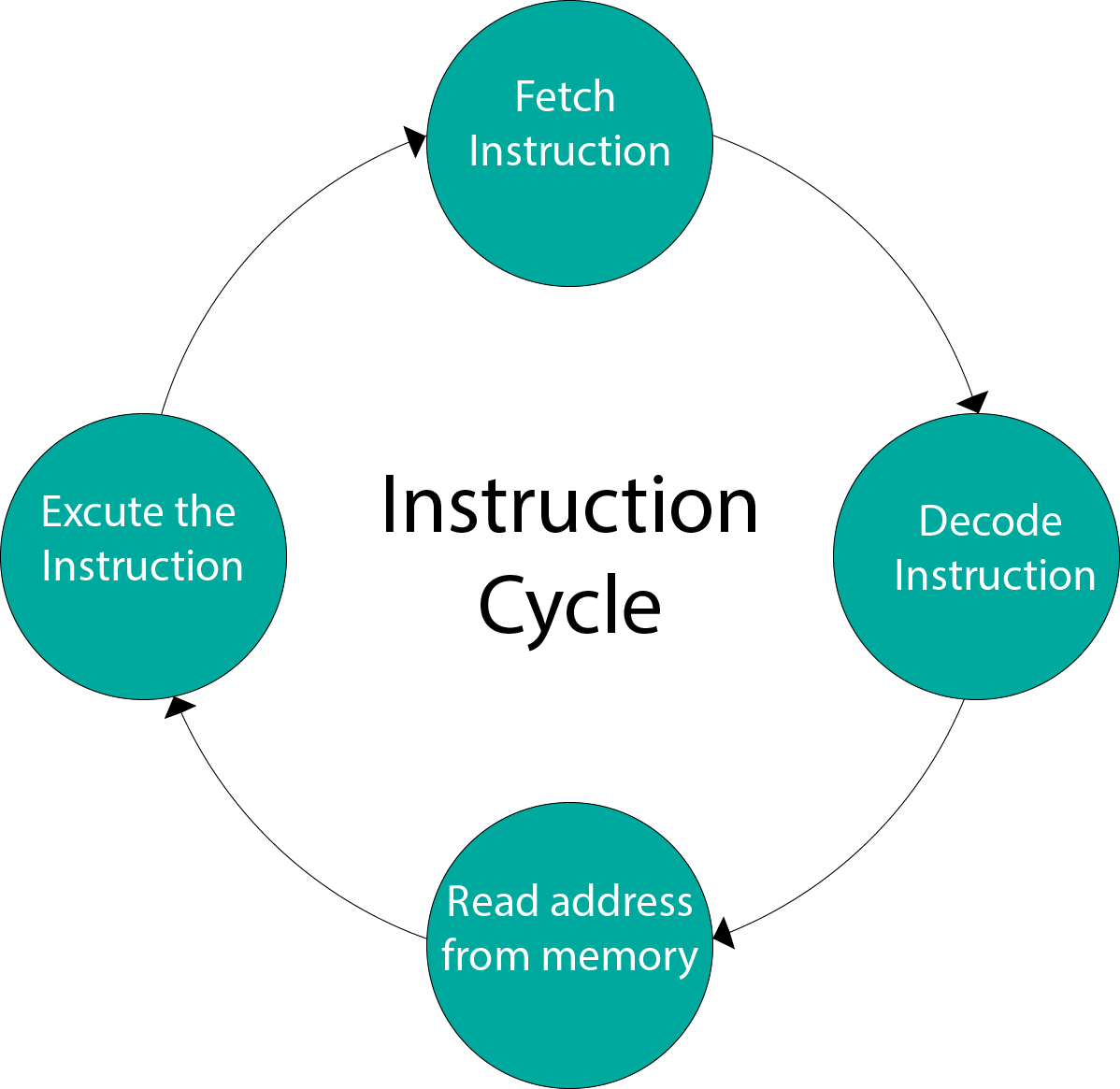
In a basic computer, each instruction cycle consists of the following phases:
- Fetch instruction from memory.
- Decode the instruction.
- Read the effective address from memory.
- Execute the instruction.
Input-Output Configuration
In computer architecture, input-output devices act as an interface between the machine and the user.
Instructions and data stored in the memory must come from some input device. The results are displayed to the user through some output device.
The following block diagram shows the input-output configuration for a basic computer.
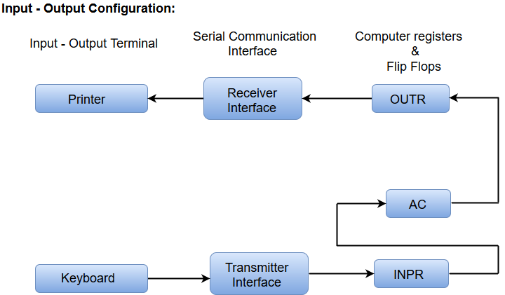
- The input-output terminals send and receive information.
- The amount of information transferred will always have eight bits of an alphanumeric code.
- The information generated through the keyboard is shifted into an input register 'INPR'.
- The information for the printer is stored in the output register 'OUTR'.
- Registers INPR and OUTR communicate with a communication interface serially and with the AC in parallel.
- The transmitter interface receives information from the keyboard and transmits it to INPR.
- The receiver interface receives information from OUTR and sends it to the printer serially.
Design of a Basic Computer
A basic computer consists of the following hardware components.
- A memory unit with 4096 words of 16 bits each
- Registers: AC (Accumulator), DR (Data register), AR (Address register), IR (Instruction register), PC (Program counter), TR (Temporary register), SC (Sequence Counter), INPR (Input register), and OUTR (Output register).
- Flip-Flops: I, S, E, R, IEN, FGI and FGO
Note: FGI and FGO are corresponding input and output flags which are considered as control flip-flops.
- Two decoders: a 3 x 8 operation decoder and 4 x 16 timing decoder
- A 16-bit common bus
- Control Logic Gates
- The Logic and Adder circuits connected to the input of AC.