What is Interrupt I/O Process
An interrupt I/O is a process of data transfer in which an external device or a peripheral informs the CPU that it is ready for communication and requests the attention of the CPU.
I/O Configuration
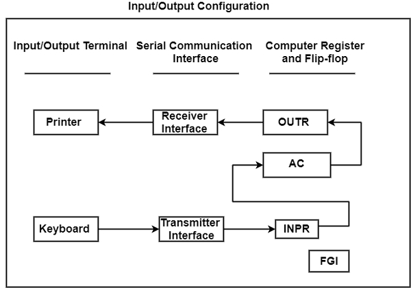
The terminals send and receive serial information. Each portion of serial data has eight bits of alphanumeric code, where the leftmost bit is continually 0. The serial data from the input register is transferred into the input register INPR. The output register OUTR can save the serial data for the printer. These two registers interact with the Accumulator (AC) in parallel and with a communication interface in a serial structure.
The Input/Output configuration is displayed in the figure. The transmitter interface gets serial data from the keyboard and sends it to INPR. The receiver interface gets data from OUTR and transfers it to the printer serially.

The input/output registers include eight bits. The FGI is a 1-bit input flag, which is a control flip-flop. The flag bit is set to 1 when new data is accessible in the input device and is cleared to 0 when the data is approved through the device.
When a key is clicked on the keyboard, the alphanumeric code equivalent to the key is shifted to INPR and the input flag FGI is set to 0. The data in INPR cannot be modified considering the flag is set. The device tests the flag bit; if it is 1, the data from INPR is sent in parallel into AC, and FGI is cleared to 0.
The output register OUTR works equivalent to the input register INPR.
The flow of data by the OUTR is the opposite of INPR. Therefore, the output flag FGO is set to 1 originally. The device tests the flag bit; if it is 1, the data from AC is sent in parallel to OUTR, and FGO is cleared to 0. The new data cannot be loaded into OUTR when the FGO is 0 because this condition denotes that the output device is in the procedure of printing a character.
Input Register
The INPR input register is a register that includes eight bits and influences alphanumeric input data. The 1-bit input flag FGI is a control flip-flop. When new data is accessible in the input device, the flag bit is set to 1. It is cleared to 0 when the data is approved by the device. The flag is needed to synchronize the timing rate difference between the input device and the computer.
The process of data transfer is as follows −
- The input flag FGI is set to 0. When a user clicks any key on the keyboard, an 8-bit alphanumeric code is transferred into INPR and the input flag FGI is set to 1.
- The device tests the flag bit. If the bit is 1, thus the data from INPR is transferred to AC and together FGI is cleared to 0.
- Then the flag is cleared, new data can be transferred into INPR by introducing another key.
Output Register
The working of the output register OUTR is equivalent to that of the input register INPR, therefore the control of data flow is in the opposite.
The procedure of data transfer is as follows −
- The output flag FGO is set to 1.
- The device tests the flag bit. If the bit is 1, the data from AC is shared to OUTR and concurrently FGO is cleared to 0.
- After that, the output device receives the coded 8-bit data and prints the matching character.
- After this operation is done, the output device sets the FGO to 1.